Dactyl Manuform III — The Build
Pre-build Component Verification
One step I highly recommend before starting is verifying that each component actually functions correctly before you solder and/or glue the components into your keyboard. I followed my own advice pretty religiously for every component, except for one component, which happened to be the one component that was actually dead-on-arrival.
Sanding/Painting the Chassis
As a young child I used to build elaborate plastic naval models, so I lucked into some experience here.
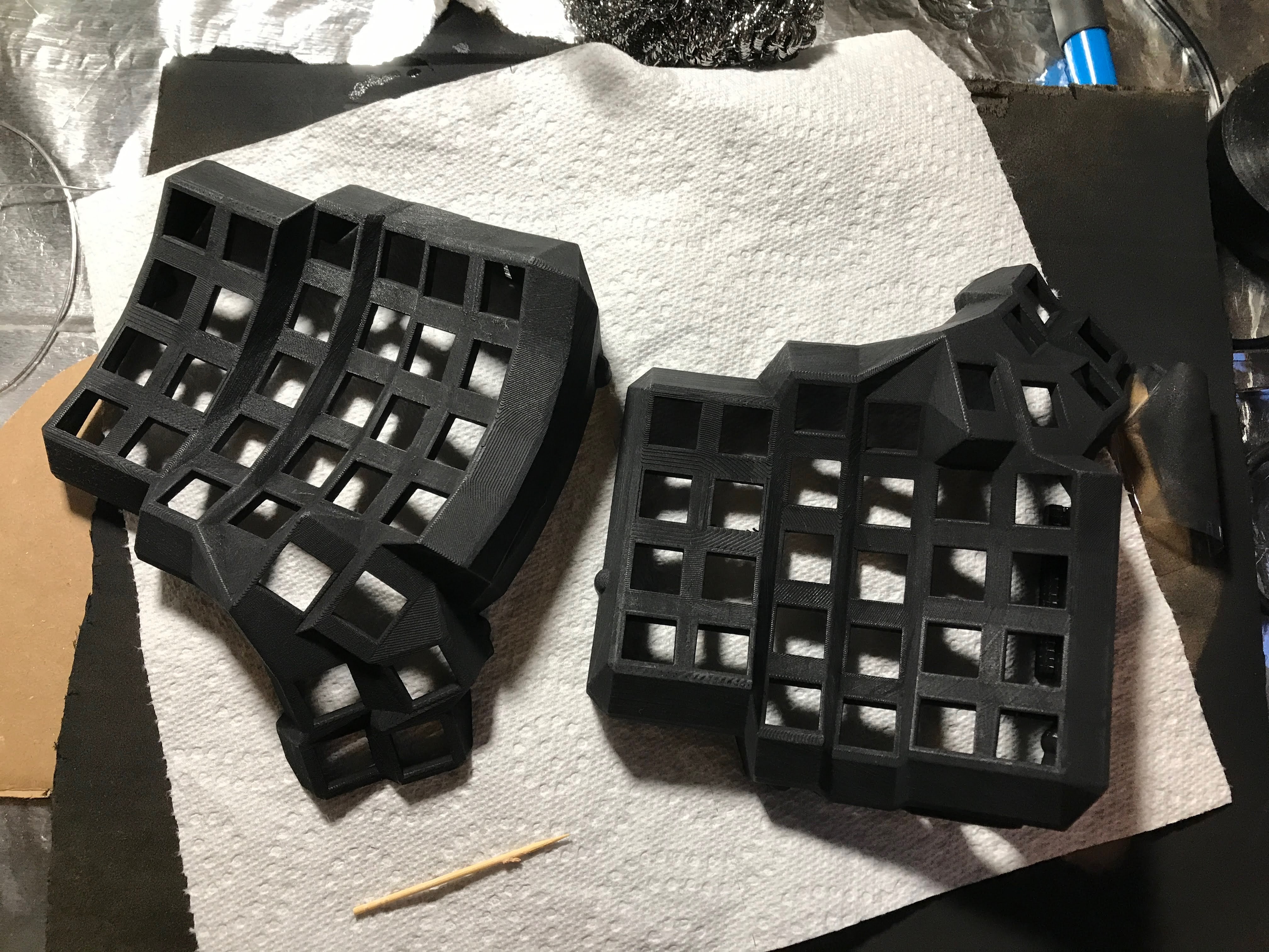
Straight off the printer—you can see the rough layer lines.
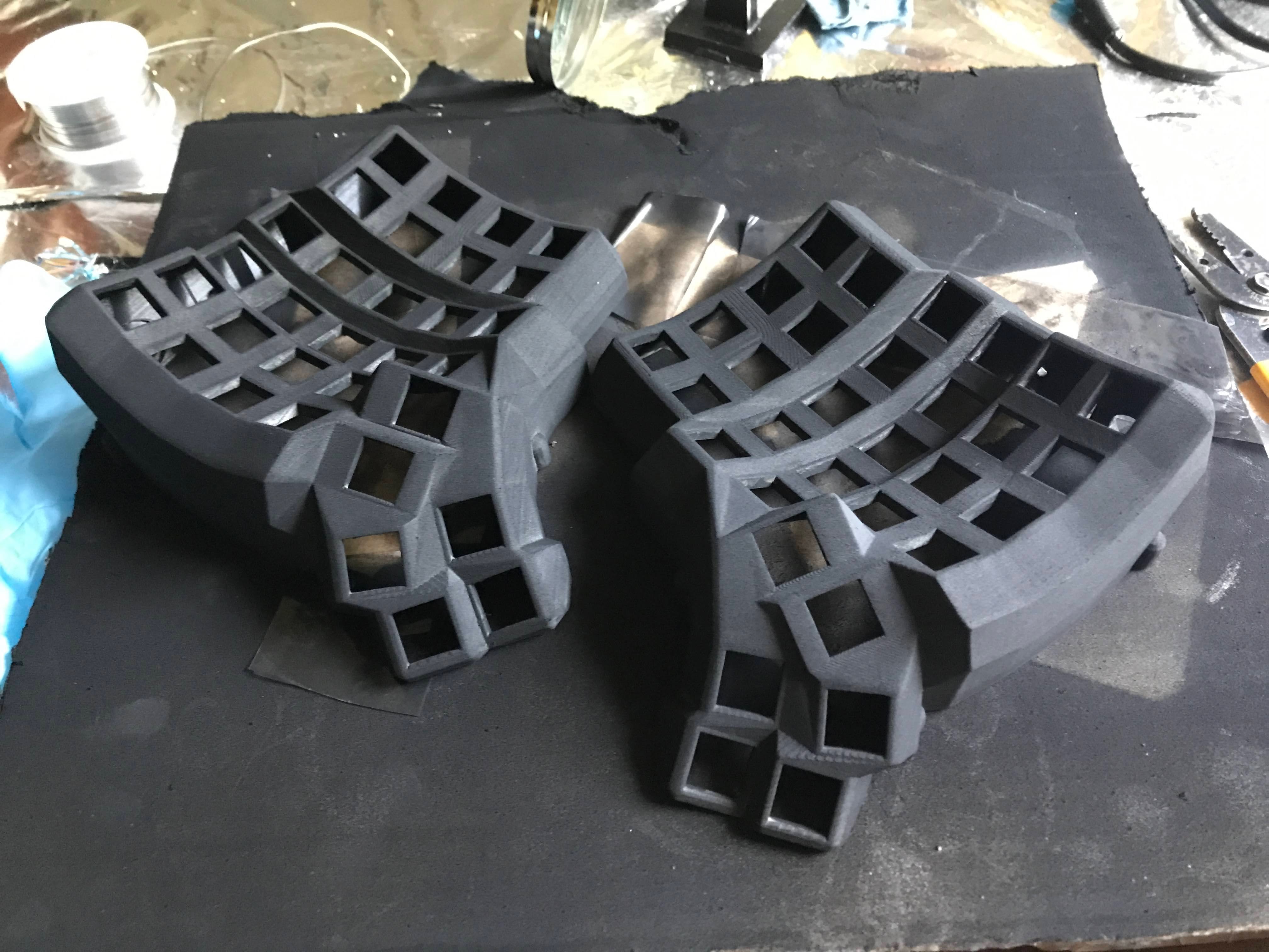
After sanding and a few coats of grey filler primer.
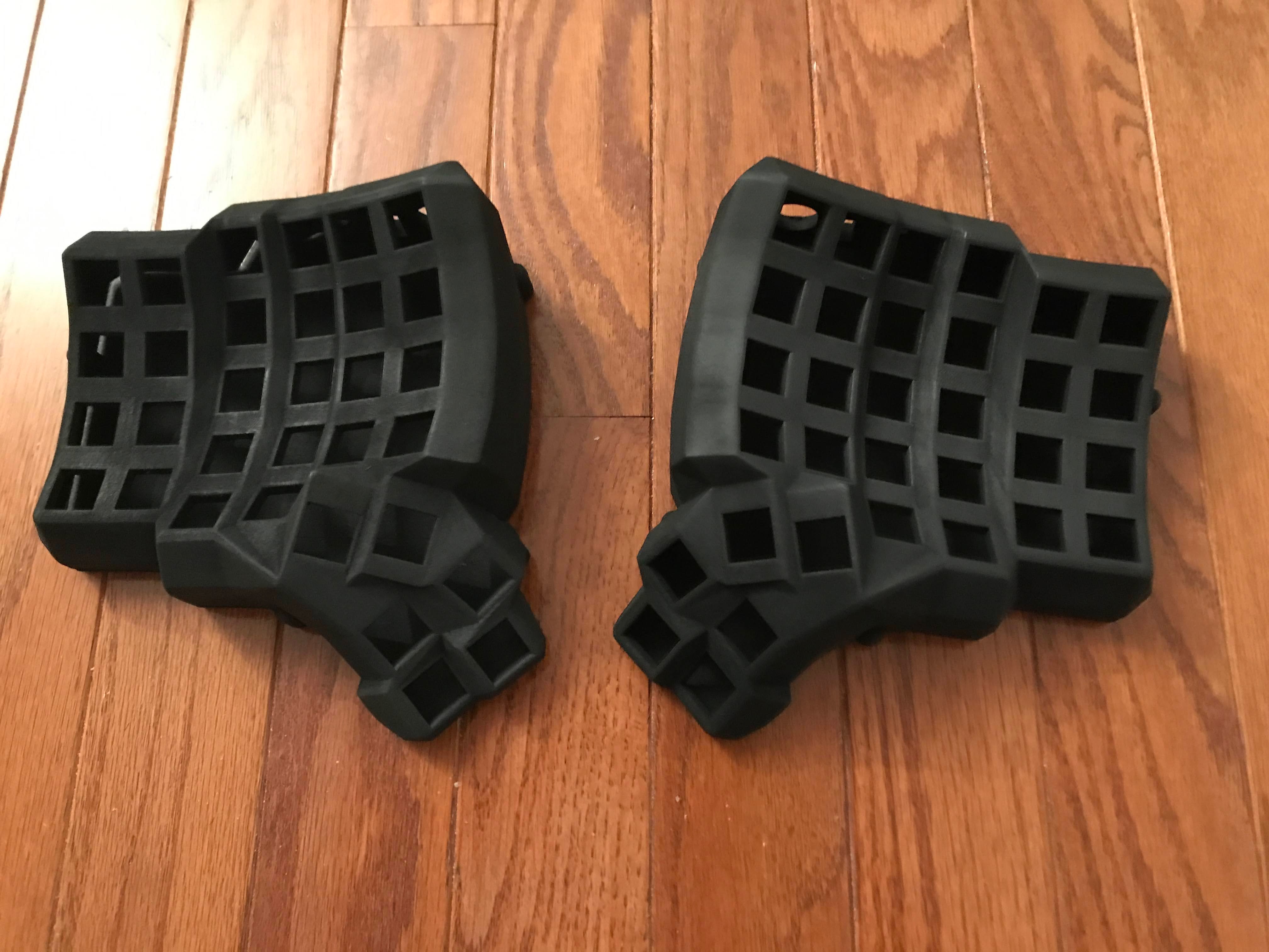
The final matte black finish.
Gluing in the switches
The friction fit around the switches isn't particularly strong, so it's a good idea to secure the switches down so you don't inadvertently pull out your wire matrix when you're just trying to swap keycaps. Although many internet guides used hot glue for this, I chose superglue instead. You just need a drop of superglue to hold it in pretty securely, and it's also not too strong that you can stick a knife in there and pry out a switch if you need to (as I had to for a few of mine).
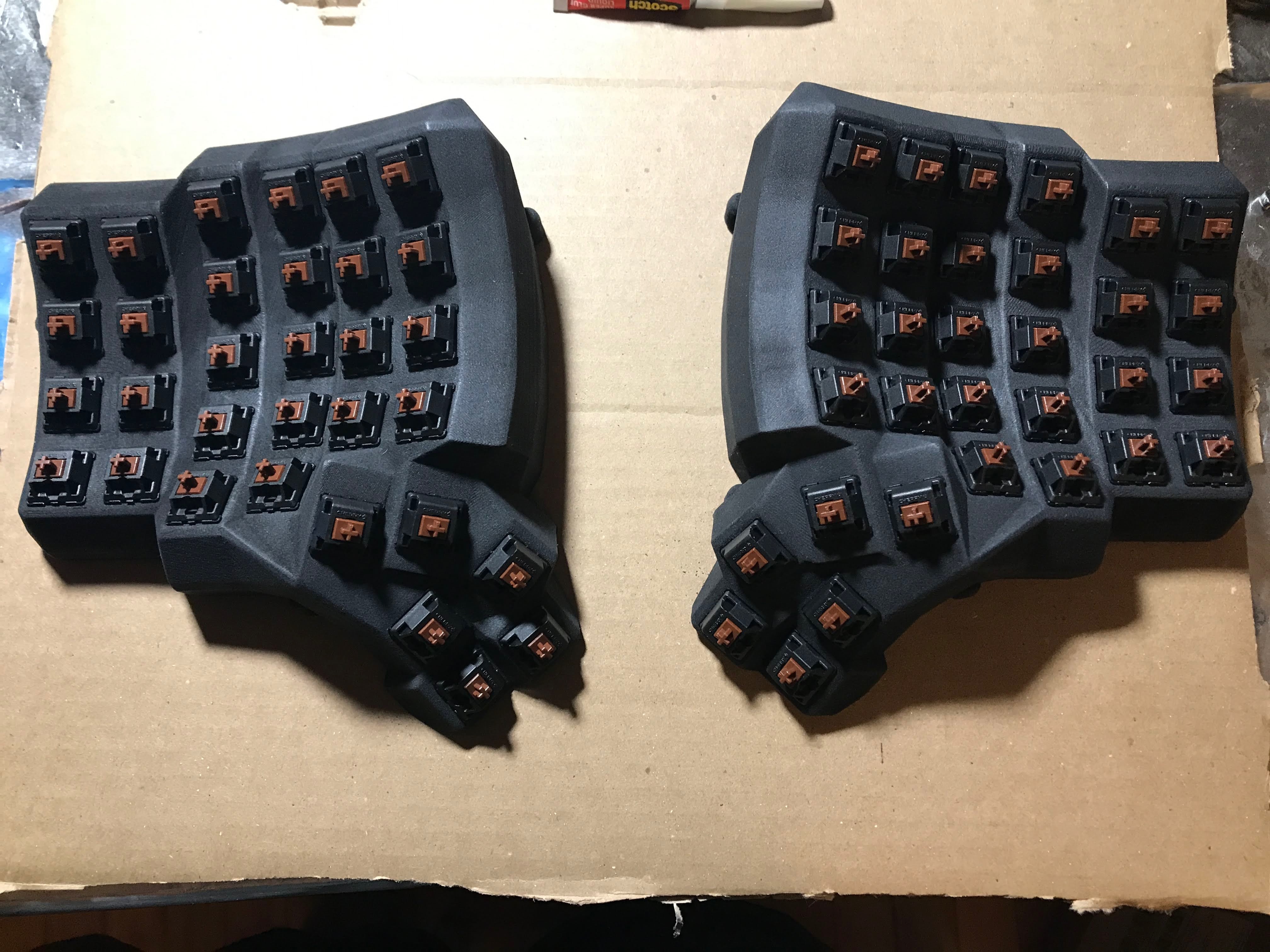
All the switches seated and glued into both halves.
A Beginner's Guide to Soldering
Learning to solder was honestly quite fun. You're basically melting these metal rods of glue that happen to conduct electricity. The basic premise is extremely simple: line up your two contact points beforehand, heat both up with the soldering iron, and touch some solder to the joint, letting it flow in, then let cool and admire your work.
Soldering the pin headers into the Elite-C's
This was the first thing I soldered. You can solder your row/column wires directly into the microcontroller, but it's a tight fit, and you have to desolder in order to switch things up or debug. I highly recommend using the microcontroller pin headers and dupont connectors, which allows you to hotswap the row/column wires. Another advantage is that you can plug the microcontroller directly into your computer, and use a double-female dupont connector to bridge pins together to test your firmware before you even wire up your switches.
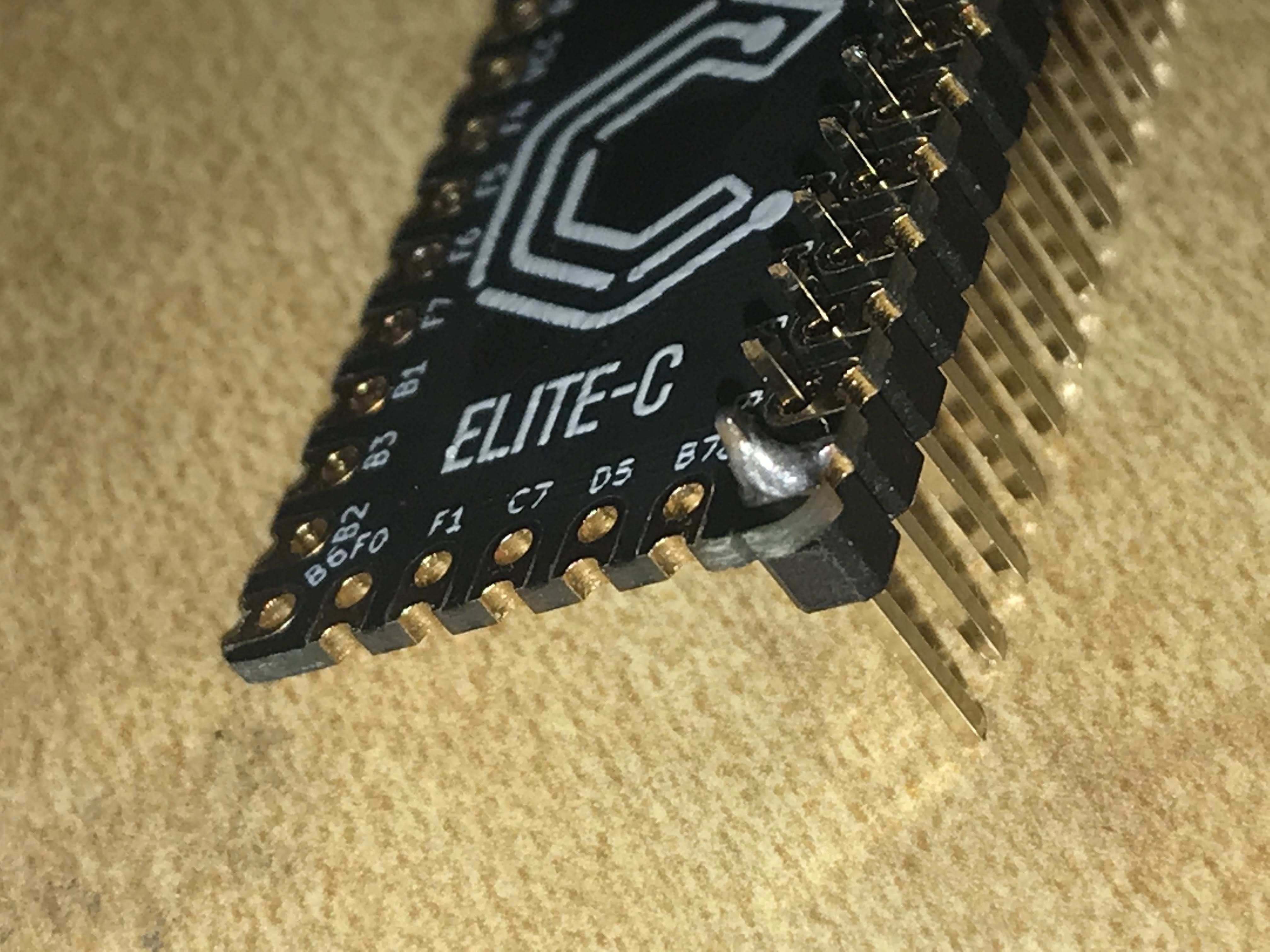
Soldering the pin headers onto the Elite-C.
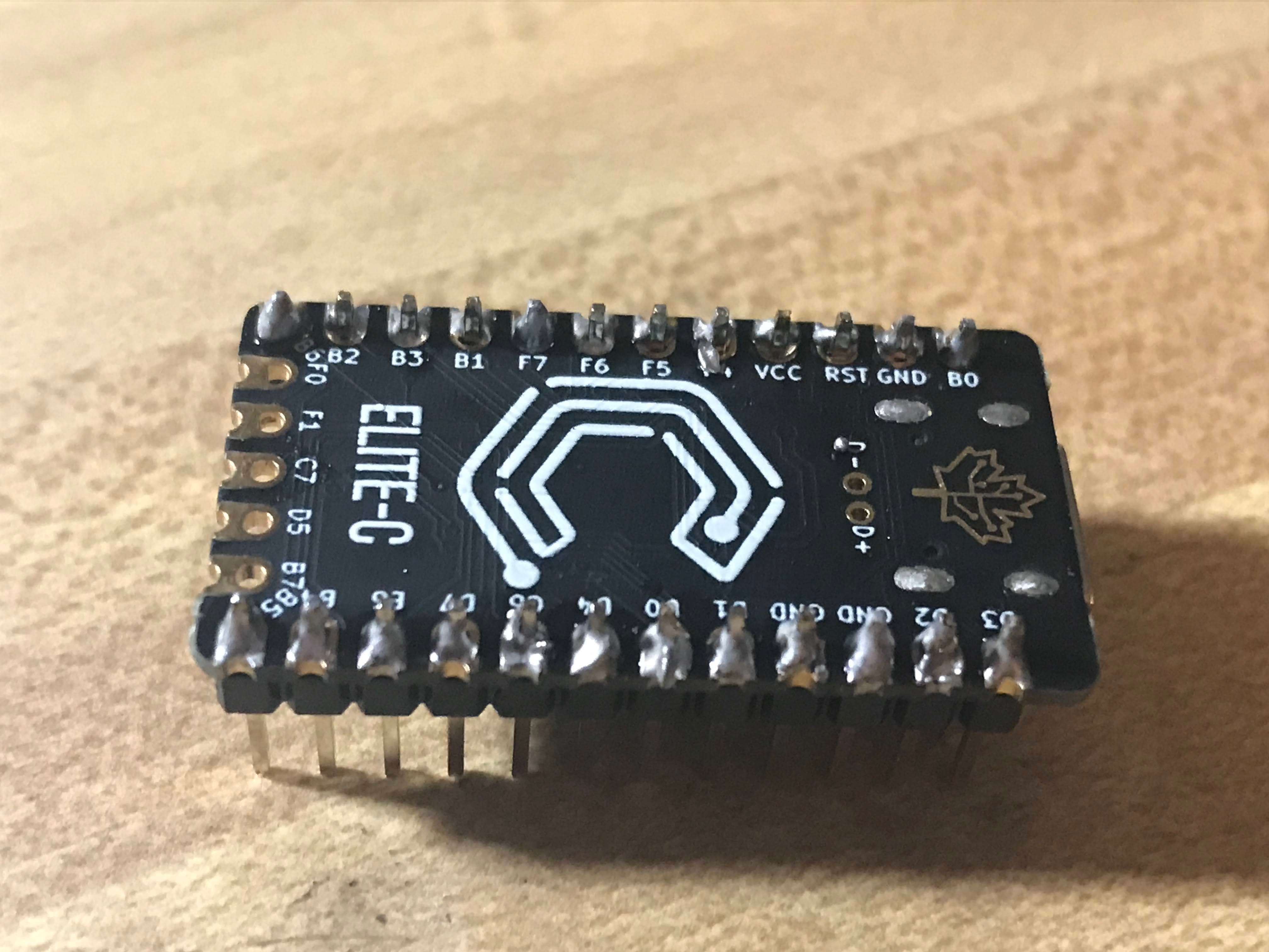
All headers soldered in.
Soldering the diodes into the Amoeba PCBs
This was the next soldering step. The Amoeba PCBs really made working with the tiny diodes a lot easier. Just bend the two ends, stick it in, solder, trim the extras. I kept the amoebas attached in the grid they came in to make handling the whole thing easier. It was quite satisfying breaking apart the amoebas at the end, sorta like a really expensive and complicated graham cracker.
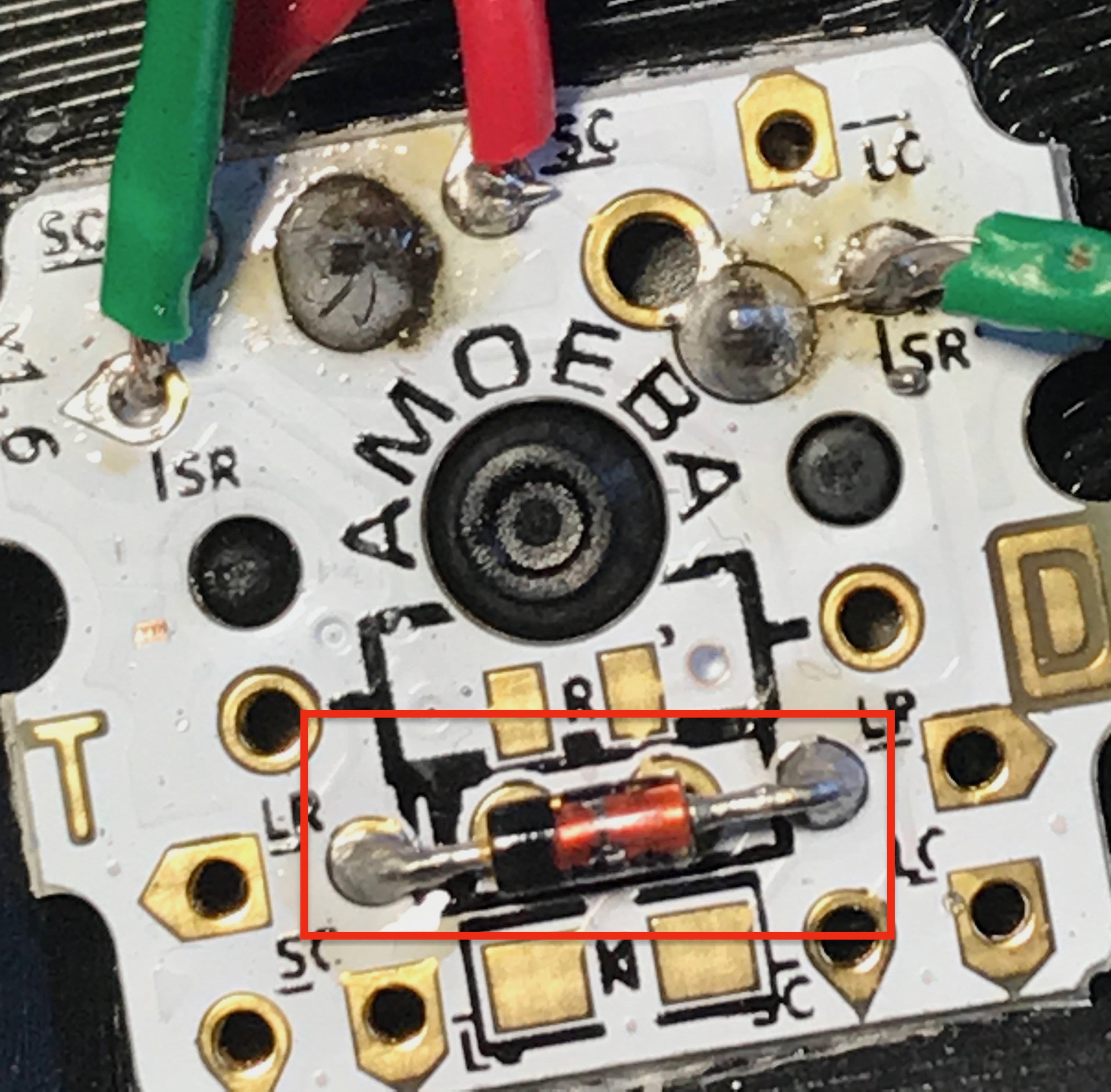
A diode soldered into an Amoeba (boxed), with the row/column wires landed on their pads.
Creating an Aviator Cable (and failing to create a USB-C cable)
I originally planned to create a matching USB-C cable to go along with my aviator halve-connector. I did in fact make a working USB-C cable, but it gave me no end of problems. I believe the pins are just way too close together to hand-solder, so my cable was constantly shorting, resulting in connectivity issues to my computer.
Prepping the conductors for the USB-C cable.
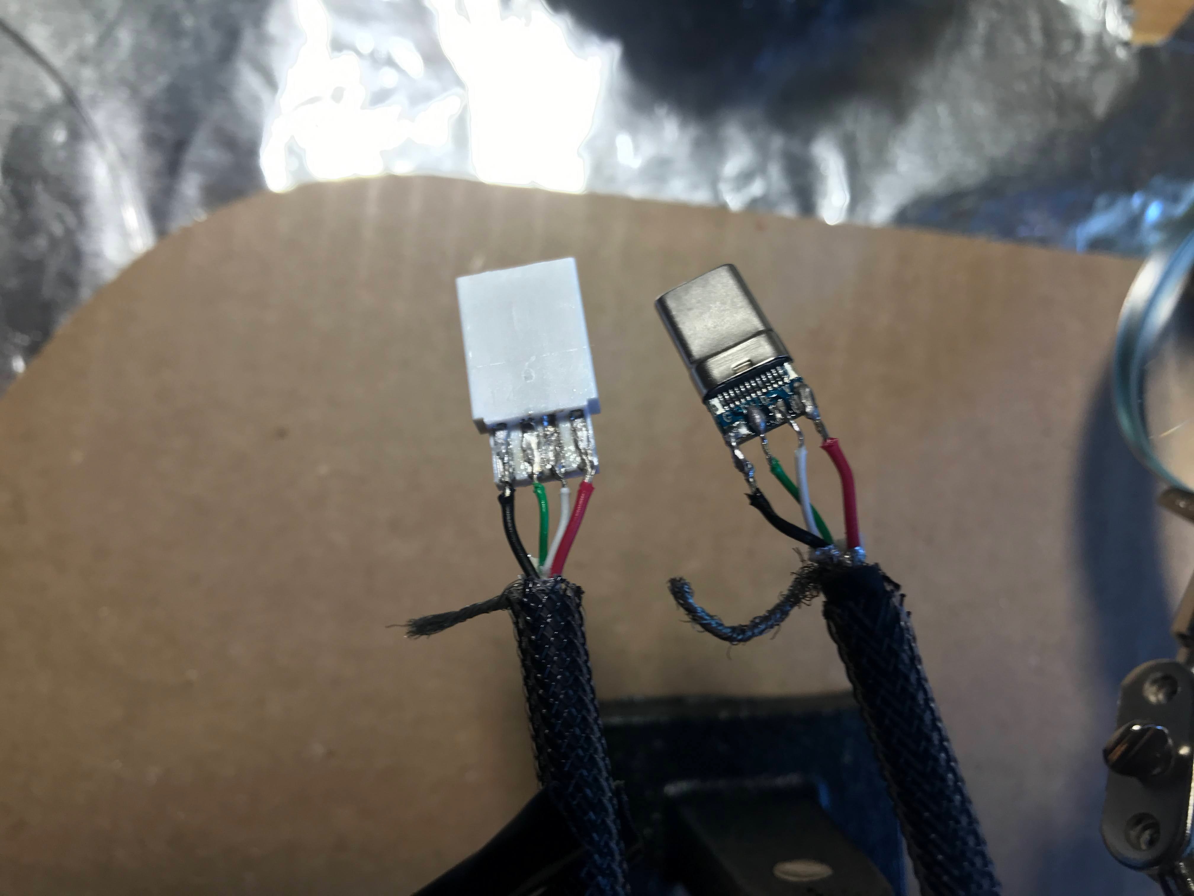
Soldering onto the USB-C connector's tiny pads—the source of all those shorts.
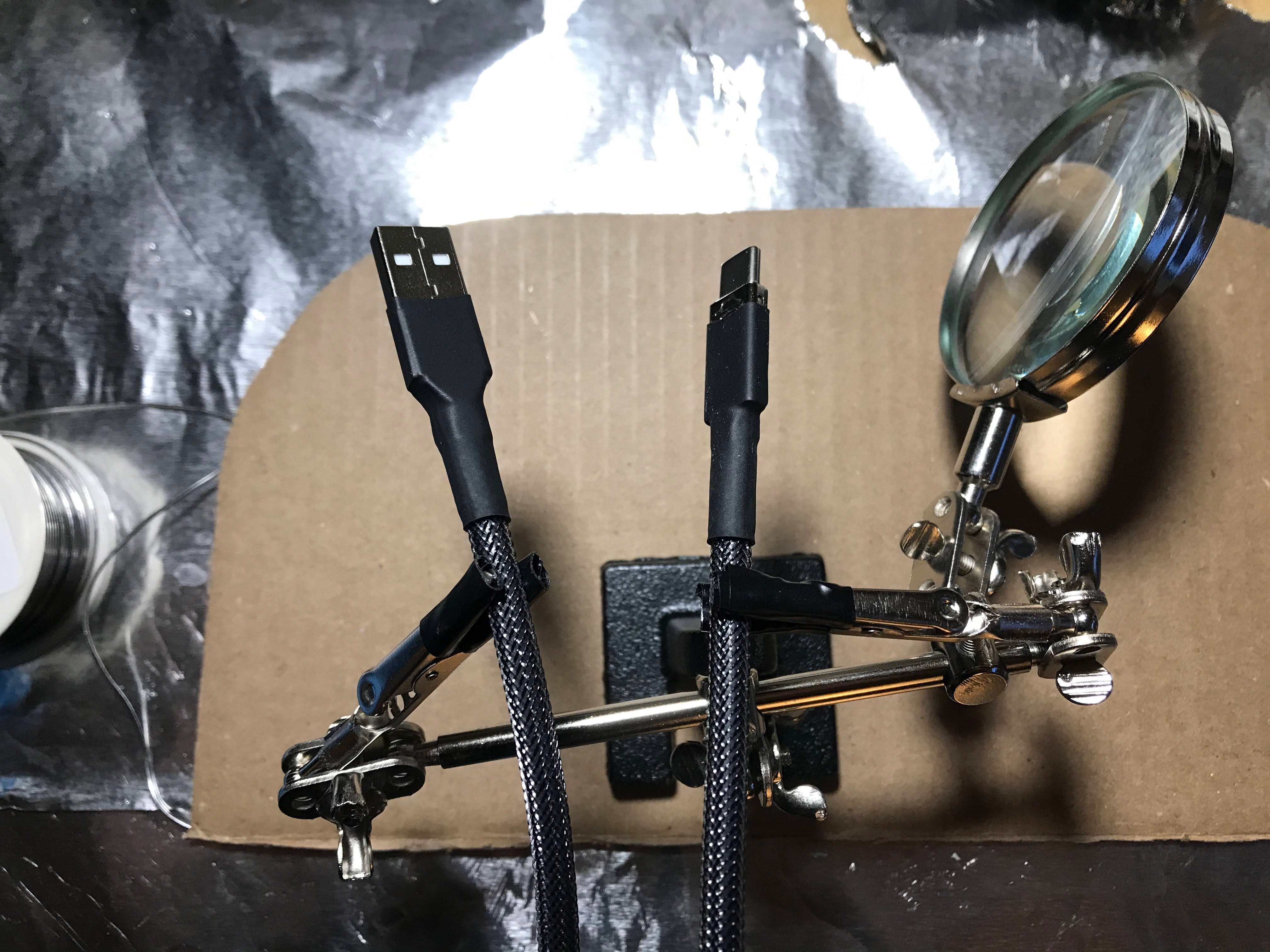
The finished cable... which gave me no end of trouble.
The aviator cable went much more smoothly, mostly because the pins you solder are 120 degrees apart from eachother since it's a 3-pin aviator.
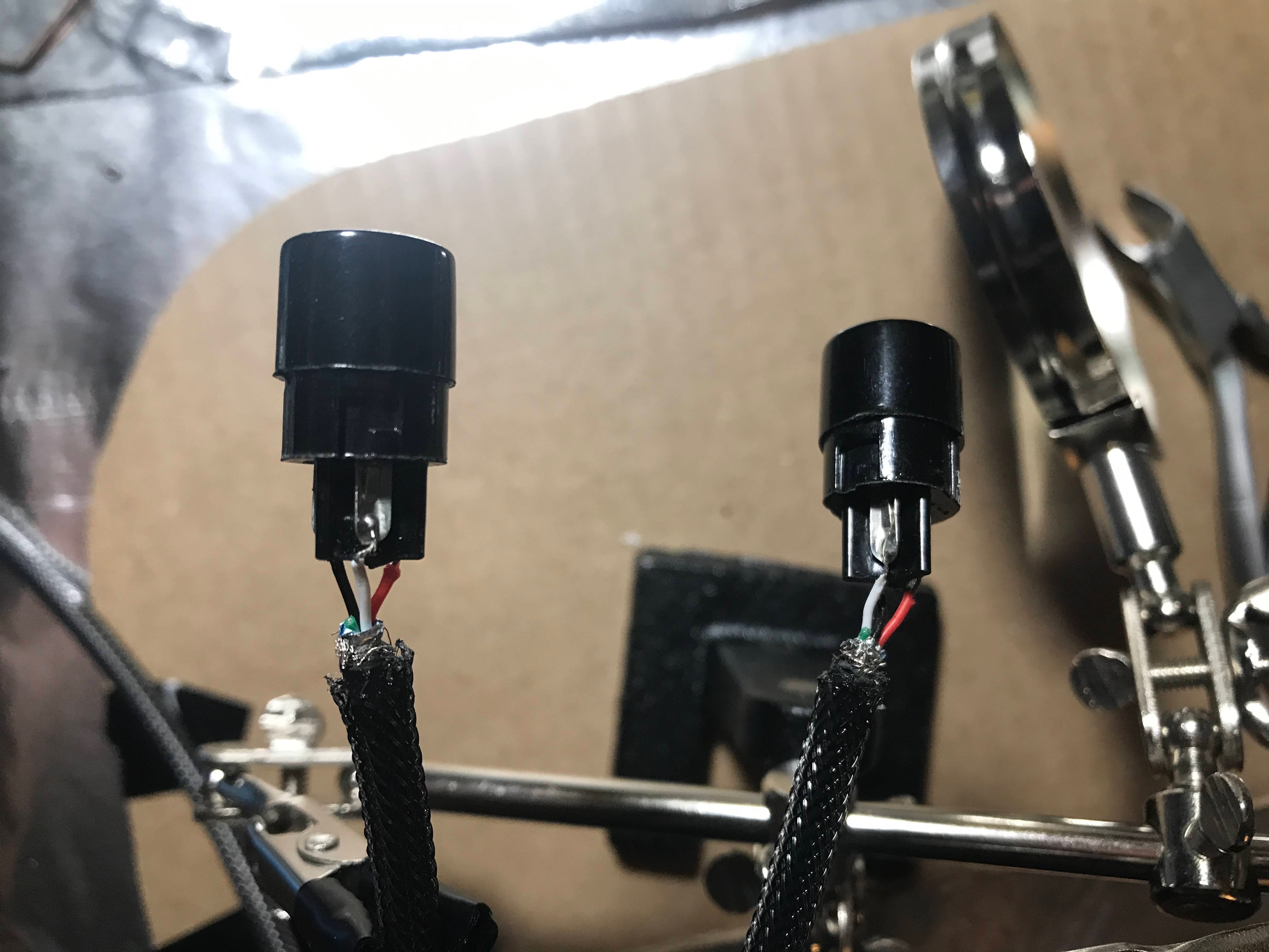
Soldering the wires into the GX16 aviator connectors.
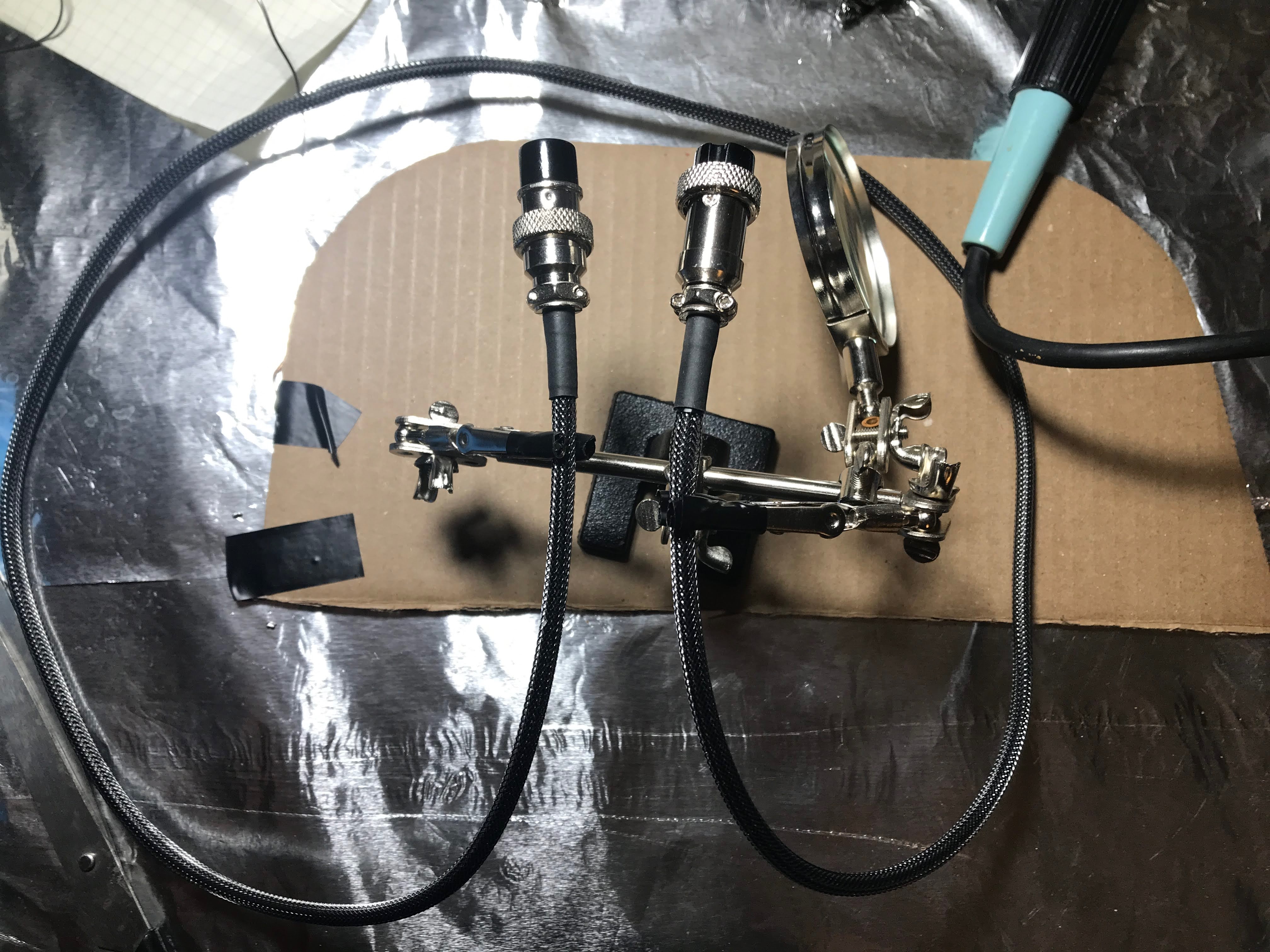
The finished aviator cable that joins the two halves.
Wiring all the Rows and Columns Together
This was the most tedious part of the build by far. My decision to use Amoebas was a double edged sword.
On the one hand, everything was really neat and cool looking. You could visually inspect and debug short circuits much easier since you don't have to overlap cables much at all.
On the other hand, there are way more connections to solder (and therefore sources of error).
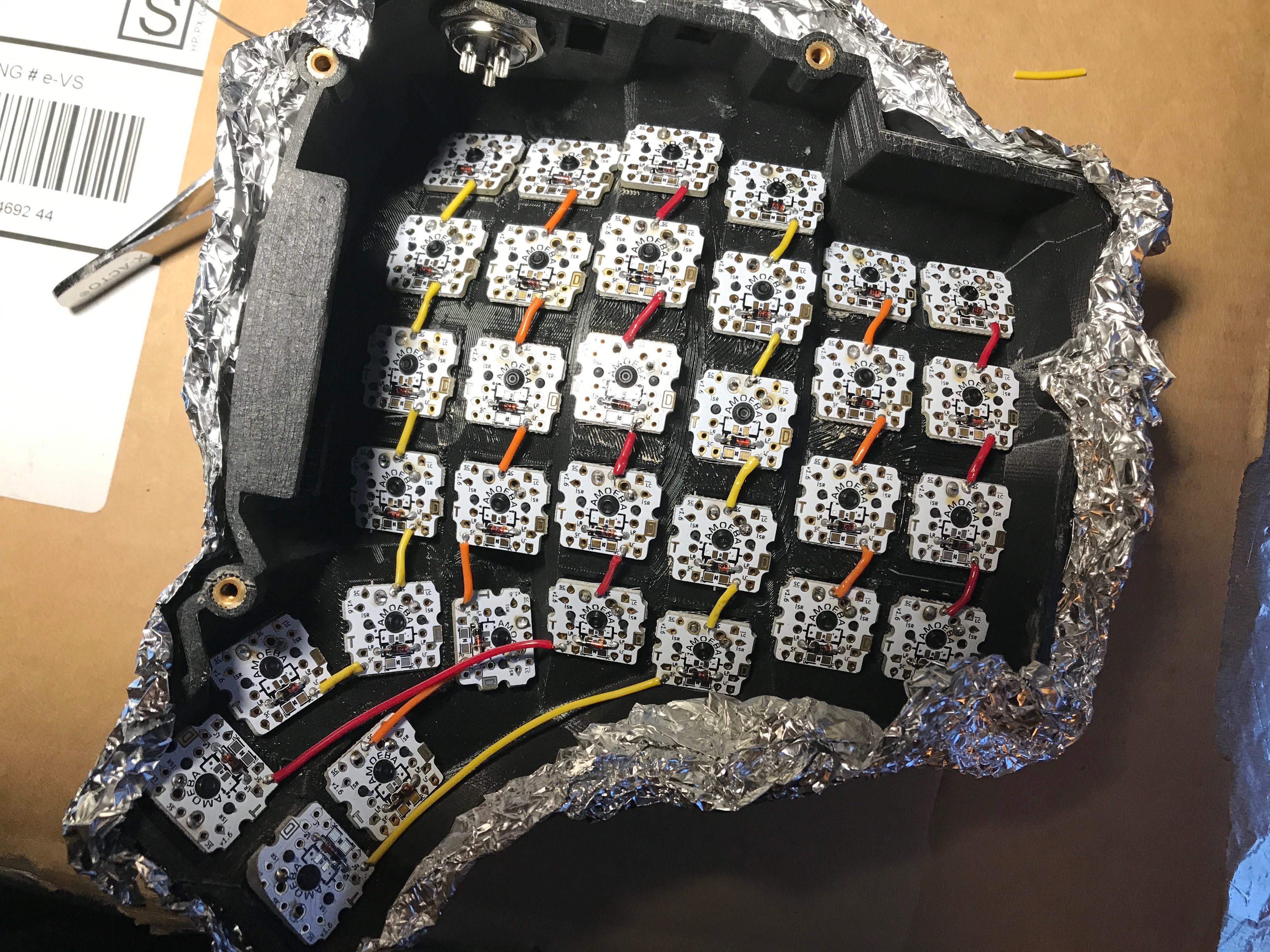
Wiring the rows together, one amoeba to the next.
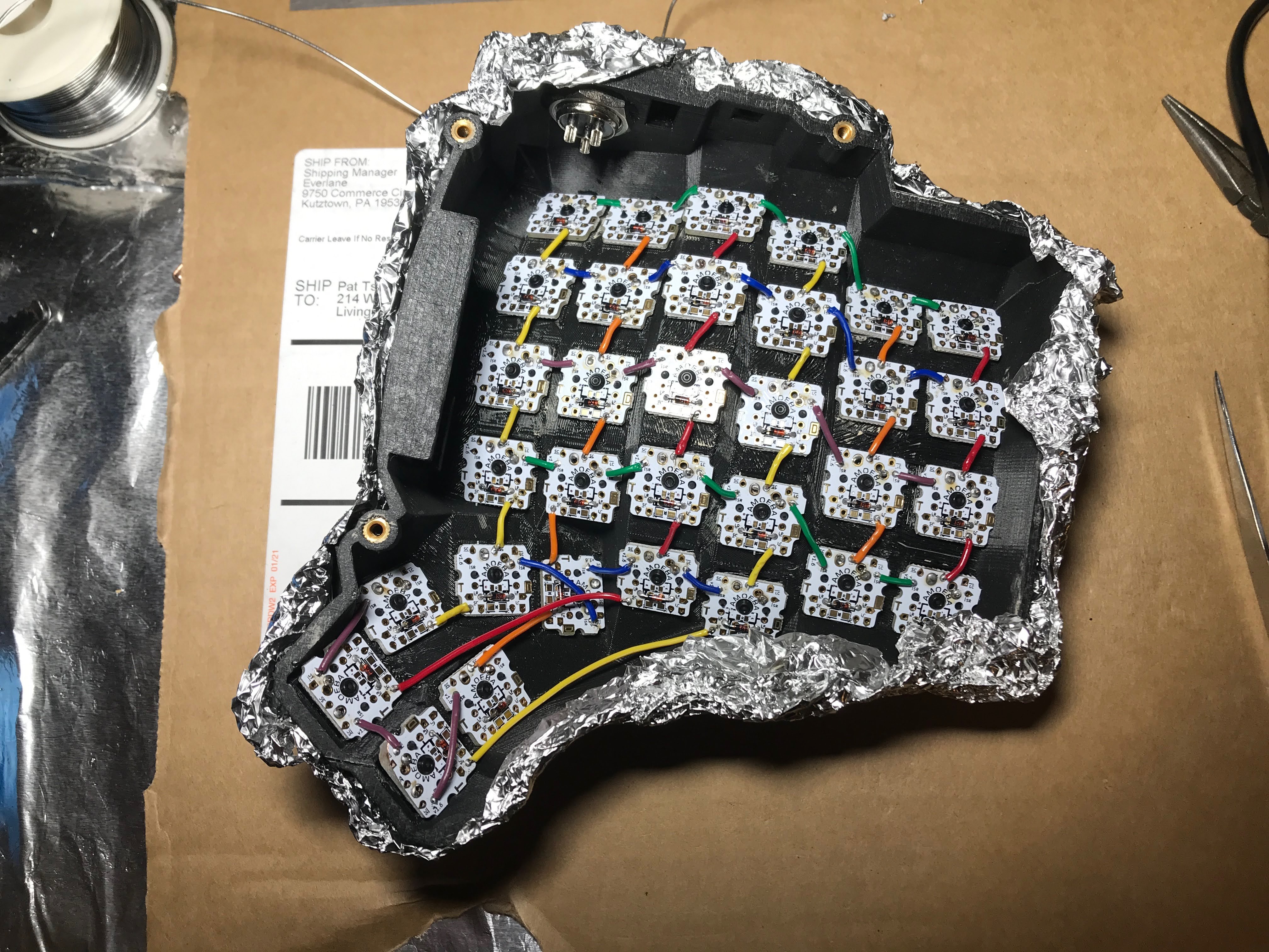
Adding the columns on top—the matrix taking shape.
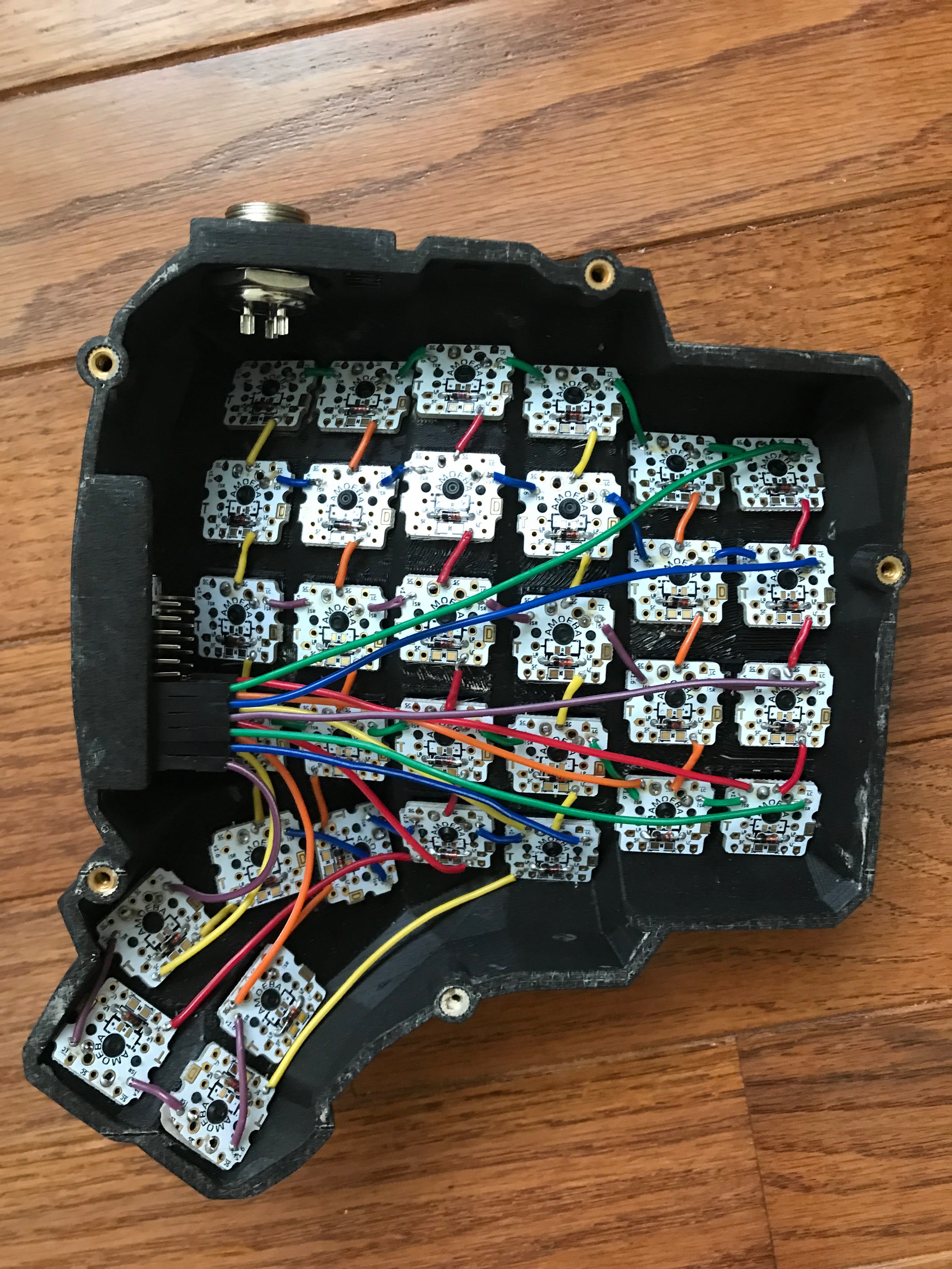
One half fully wired, every row and column routed back to the controller.
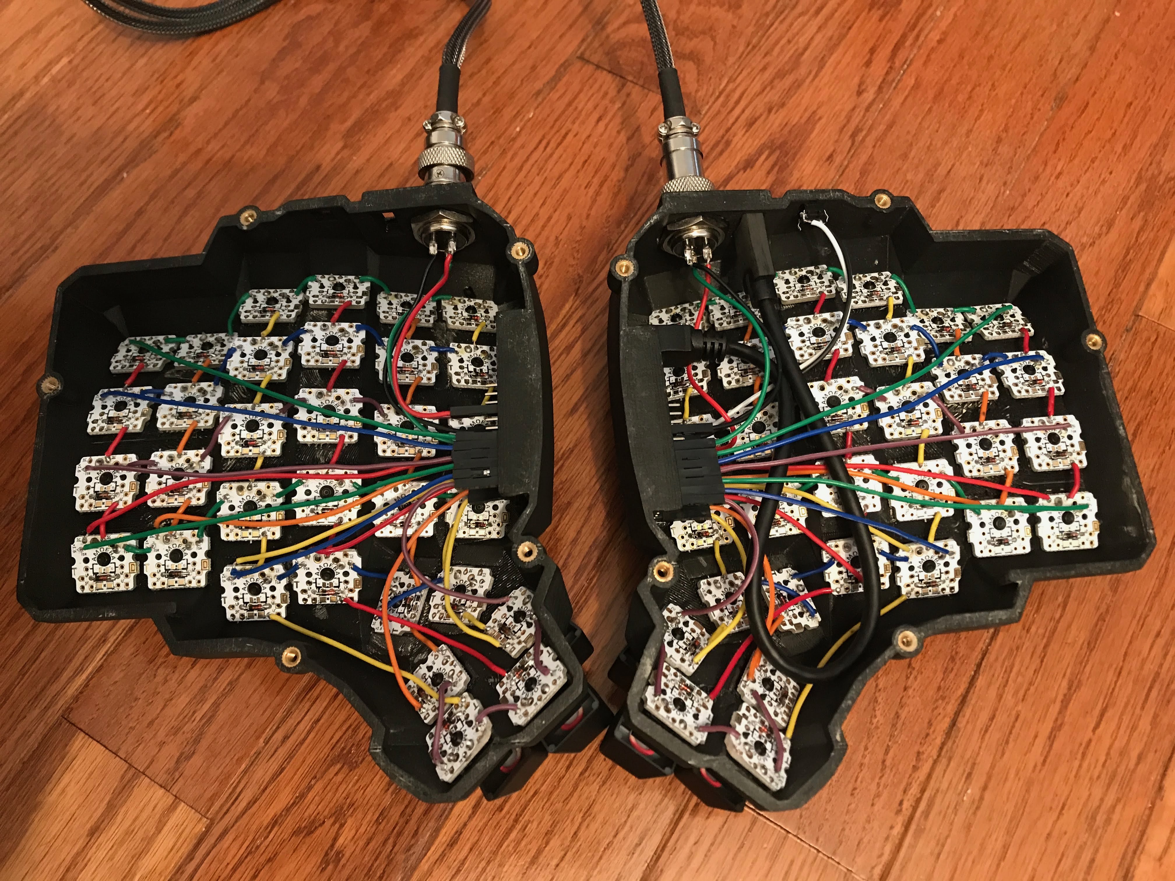
Both halves done—color-coding the wires made debugging so much easier.
Things that didn't go according to plan
- clearance near thumb cluster for amoebas. I had to un-superglue 3 switches on each half to reorient the amoebas. Luckily prying them off didn't crack the cases. And even worse, the furthest down thumb cluster button actually has a clearance issue with the case bottom. So I had to sand down the PCB corner for the case to close properly. I had to sand so much that I actually wore away one of PCB (unused) sockets. I was worried that I might have destroyed some critical connection, but it seems to work fine.
- stranded wires suck.... need to twist them carefully and tin them before use, which takes a ton of time. I will definitely go with solid core wires next time, and I might even consider not using amoebas, because they really require you to measure, cut, strip, twist, and tin a lot more connections. Using a single solid core wire would require just an initial measure/cut, then a strip per switch.
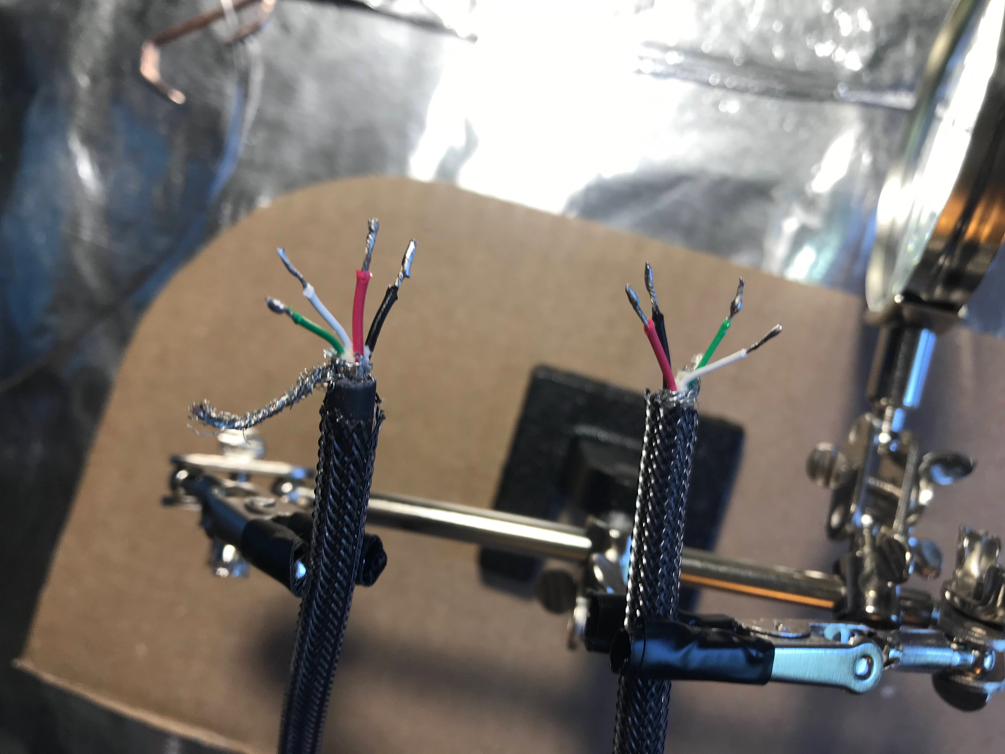
- USB-C extension cord... The one I bought had a head that was too long and didn't fit. I thought "no worries, I have an extra USB-C head, let me just splice off the long connector, shorten it, and install my own 90-degree connector. When I cut the wire open and examined it, to my utter dismay, I didn't see the expected 4 wires of color black, red, white, and green, but rather like 13+ wires... It turns out USB 3.0 has many additional connectors. I did see some red, black, green, and white wires, and looking up the spec online said that those four were used for USB 2.0 connections, however, there were duplicates of them, and I wasn't confident I'd pick the right ones. So I just ordered another, this time 90 degree USB-C extension.
- soldering iron oxidized very quickly, I still don't know how to properly take care of them
- Making a USB-C cord is really quite difficult, the connectors are way too close together
- The first reset switch which I soldered and superglued in was faulty. I don't know why I didn't test this before going forward, since I pre-tested basically every other component. I guess since this was the very last thing, I was in a rush to get it plugged in.
- Of all the 300+ soldier joints I created for this keyboard, none failed, however I put a single joint in the wrong place. I had to undo that joint and pick the right socket on the amoeba PCB
- I had to tweak the C firmware a bit for the pins for the right-hand (non-master) side of the keyboard. I ended up needing to do a mirror transformation on the ordering of the pins, which I was too lazy to actually figure out, so I just kept reversing and swapping things until I got it right. This proved quite tedious since I had to plug the secondary half directly in to flash it, then plug it in as a daisy chain off the other master to test it.
- Rosen core lead/tin solder was definitely toxic. I had a strong window fan exhausting all the air outside, which did a decent job removing solder fumes, but I still had a headache after soldering for too long. I was also OCD about reducing lead exposure and cleaning all user-facing surfaces two or three times after completion. I think next time I'll go with lead-free solder for the peace of mind.
- It's surprisingly hard to find a deep black spray paint. Two of the sprays I tried just ended up being a deep dark grey. I actually found a video online where a guy compared the blacks of 10+ different brands. But I didn't feel it was worth it to go out just to buy a deeper black paint.
- Wood filler doesn't do much to aid in creating a smooth surface. I ended up just sanding it all off and sanding smooth the layer lines. Next time I'll maybe use 3d liquid resin designed for 3d printed parts, or maybe just rely on straight sanding.
- removing solder is... surprisingly impossible without additional tools. You're supposed to use a solder wick or a vacuum pump to remove solder. I tried just cleaning my iron and drawing the solder up via capillary action, or using another clean wire to pull the solder up, but gravity and the surface structure of the joint meant this never worked. I have a handful of joints that are horrendously over-soldered because of this.
- My self-made USB-C cord ended up causing me tons of problems. I think the inner wires are just too close together to solder properly without shorts. I was having this problem in Windows where the keyboard changed in the device manager from "USB Keyboard" to "Unknown USB Device", at which point it would stop responding until I unplugged and replugged in the keyboard. In Mac, it would say "Unplug USB device using too much power to re-enable USB devices". At first I thought this was a firmware configuration issue. At which point I tried to flash a lower power usage setting. And in the middle of flashing, my USB cable shorted, which resulted in my elite-C microcontrollers having corrupt bootloaders that wouldn't take new flashes. I then proceeded to purchase a new pro-micro controller to function as an ISP so I could restore my elite-C's back to working order. One week later, I got the pro-micro in the mail, quickly soldered all the pin-headers in, and prepared the ISP firmware onto it. Before wiring it up in ISP flash mode, I tested out the elite-C's one last time... and they were working... They took new firmwares via DFU perfectly. The only hypothesis I have is that I somehow put corrupt data into the temporary memory. And it took a full week for that temporary memory to fully clear out? I don't know, this explanation doesn't make a ton of sense to me, but I'm not complaining. Well, now I have a few extra pro-micros, which will probably be useful when I build a second dactyl.
- Lead solder paranoia. If you look in my pictures, the keyboard outside is strangely wrapped in aluminum foil. I did this because I wanted to keep lead cross-contamination to a minimum. I didn't want extra traces of lead over the keyboard surface which I'd be touching every day. This also meant that I wore nitrile gloves every time I soldered, and I wore them every time I touched the internal wiring of the keyboard. I didn't really think about this when I purchased the lead-based solder. I went off advice of other keyboard hobbyists who suggest the leaded solder because it's easier to work with, which would be important for a beginner. I still think leaded solder is probably the right choice, and will use it for my next build. There are two primary reasons. 1. lead-free solder has a higher melting point, which makes it harder to work with and also releases more rosin flux fumes, which are arguably worse for health than contact with leaded solder (soldering temperatures are far too low to vaporize lead). 2. lead-free solder is more brittle and less reliable. Even with leaded solder I have issues with the joints sometimes breaking after the fact (also probably due to inexperience), and I imagine the problem would be even worse with lead-free solder.
- Three weeks into using my keyboard, I noticed that sometimes the tab and tilde keys would stop working. And then after I pressed down harder on them they would start working again. I opened up the case and realized that I hadn't actually soldered two of the joints to these two keys, and it had just been relying naked contact, which explains why it would randomly stop working due to motion.
Things that went well
- matte clearcoat surface feels great. The keyboard had a grainy feel after just initial painting which I was worried about, but the matte clearcoat feels smooth and durable.
- color coding wires was a lifesaver for debugging. It made it much easier for me to figure out which row/column was miswired. It also looks super cool!
- helping hands was initially thought to be an unecessary purchase, but I found it super useful for small delicate jobs.
Less is more, except when it's not
I'm a general proponent of the "less is more" philosophy with almost everything, and I thought soldering would be the same. I thought generally I'd use the minimal amount of solder necessary for the task in order to be really clean and organized. That's true... to an extent. Generally a solder joint shouldn't be a total overflowing glob of solder, however using too little can result in an inproper join which might not have a full electrical connection. The best technique is to fully saturate the joint with enough solder, let it heat for a second or two, and properly bind the wire to the joint. This best reduces the chances of a "cold join".
Furthermore, when "tinning" the soldering iron, it's actually important to fricken cover and glob the thing in solder, especially when you let the soldering iron cool down to be put away. That thing oxidizes crazy fast, and the safest way to ensure long life is to put a thick disgusting layer of solder on it. Only reduce the amount of solder from the tip when you're actually about to solder, and then glob it back on when you let it cool. Before this technique, I oxidized the crap out of a brand new tip in about 20 minutes. It probably didn't help that I aggressively used steel wool on this new tip.